Saturday, November 27, 2021

Arduino programming

For this week, after learning about the Arduino board and some components that can be used with Arduino board, we were tasked with 4 tasks.
  • Interface a Potentiometer Analog Input to maker UNO board and measure its signal in serial monitor Arduino IDE.
  • Interface an LDR to maker UNO board and measure its signal in serial monitor Arduino IDE.
  • Interface 3 LEDs (Red, Yellow, Green) to maker UNO board and program it to perform something (fade or flash etc)
  • Interface the DC motor to maker UNO board and program it to on and off using a push button on the board
I was not able to participate in the on-campus practical as I was having a fever, I would be using photos of the aurdino board from my teammates. 

Firstly. I used thinkercad to trial the codes. I also have embed my finished work on thinkercad. 

With the help of my teammate, i was able to design the board and the code needed to measure its signal.

potentiometer


The LED began flashing when the board was physically replicated. The frequency of the LED may be changed by rotating the potentiometer. The frequency of blinks drops as I crank the potentiometer clockwise, but it increases as I turn it anti-clockwise. This is due to the fact that turning the potentiometer clockwise increases the resistance. The sensorValue will increase when the resistance rises, causing the LED to blink less frequently, and vice versa.
In order to measure its signal in the serial monitor, I added Serial.begin(9600); under voidsetup and Serial.println(sensorValue); under voidloop so that the serial monitor will monitor the sensor value which is the potentiometer. Whenever I turn the potentiometer, the serial number will change.


A: At lowest point (Left side of the meter)
B: Turning to the middle point 
C: Turing to the end point (Right side of the meter)


LDR

For the LDR, I know that the LDR has to be in series with the LED so that the LED will be affected by the LDR. So this is how it looks like in tinkercad.


I also wanted the LED to blink continuously and for the LDR to modify the brightness of the LED as the light intensity changes. I understood that as the light intensity increased, the resistance of the LDR decreased, and vice versa, thus the LED would glow brightest in a bright room and dimmest in a dark room, based on my previous experience. The blink LED will have the same code as activity 1. My theory is correct after testing it with a real board. Here's a shot of the LED.


3 LEDs

I was able to connect the three LEDs (Red, Green, and Yellow) to L13, L11, and L9 on the board in Tinkercad using what I learned in the first assignment. I also need to program it such that all three LEDs blink in unison in a loop. This may be accomplished by three times replicating a single LED flashing code and changing the L. (value). Here's a screenshot of my Tinkercad. The delay is 1 second and may be adjusted by adjusting the delay value ().


DC motor


Thursday, November 11, 2021

Laser Cutting


Week 2 Practical

For this practical, we were taught on how to use the laser cutter and its operating procedures during the previous tutorial lesson.

Here is our improved SOP

SOP Group 3

Activity: Operation of the laser cutter


Start up of the laser cutter

  1. Turn on Air compressor (Skip for fusion Pro)

  2. Turn on the fume extractor.

  3. Turn on the laser cutting machine

  4. Turn on the PC


Operation of corel draw

  1. Open CorelDraw on the computer

  2. Import desired  BMP, PNG, JPEG, DXF file or SVG file into CorelDraw 

  3. Click on the cursor tool on the left panel and select desired line/shape

  4. Change the colors of line/shape to desired operation 

(Red=vector / Green=engraving)

  1. Send the imported file to print (Ctrl-P) then press print.


Operation of epilog dashboard

  1. On the Epilog Dashboard, choose Autofocus:Thickness (Pro) / On (M2) on the top of the right panel

  2. Turn on Air Assist on the bottom of the right panel

  3. Load Material Library to choose what material is being cut/ engraved

  4. Add final adjustments to the materials position and the speed/power/frequency desired. Check with the personnel in charge if unsure 

(For both machines, position the object to cut at the top left corner so that the laser need not move too far to start cutting)

  1. Press the print button


Operation of 3D printer

  1. Check the file’s name and estimated time to cut on the LED Touch screen(Pro) / LCD screen(M2). Once confirmed, press the PLAY/GO button to start cutting.


Shut down of laser cutter

  1. Clear all material from inside the laser cutter

  2. Turn off the laser cutter

  3. Turn off the fume extractor

  4. Turn off the air compressor

  5. Shut down PC


I have also included pictures on the software interface.


And here is how you actually get your design printed

Here are the pieces my group have cut out


Reflection

We learned how to use the Fusion Pro and Fusion M2 to accomplish laser cutting in this practical. We were initially put to the test on the competency exam, and we quickly saw that our SOP was lacking in-depth, but we were able to operate the machine owing to Mr Chan and the supervisors. After that, we realized that owing to kerfing, all of the parts were not a perfect match, so we went back and tried to redraw all of the components on Fusion360. However, we had to postpone the cutting owing to some technical issues with our laptops. When we returned to FabLab the next week, the wood we used was a different size than what we had the week before. The parametric measurements are then changed to adjust all of the gaps. We were able to adjust all three drawings to their proper size in a matter of minutes. To account for kerf, we had to narrow the distance even further. Finally, using a 4mm wood thickness, we reduced the gap size from 4.5mm to 3.5mm. The components are also in perfect harmony with one another. We initially felt that adding parameters was just an extra step that was unnecessary, but after needing to make rapid adjustments to the slot width, we realized that it was highly beneficial and that it should be included in all of our future auto fusion360 designs. Rather than recreating all three components, which would take around 20 minutes, we just had to alter the settings for all of them, which took four times as long. We were quite thankful for this function and realized how important it was while we were doing it. We also saw the value of kerfs firsthand when our initial attempt failed to hold together, and all of the other groups struggled as well. We talked and decided on a gap length that will fit after looking at the efforts of other organizations. As a result, on our second try, we were able to acquire a great fit. We were able to develop a basic yet efficient IPad stand design using the components we created via laser cutting. The foundation of the stand is made by joining three square pieces to a rectangle piece, and the handphone stand is made by joining two more rectangle pieces to the structure.

Friday, November 5, 2021

Cad for laser cutting

 For this blog, i will be showcasing my journey on how I design an handphone stand to be laser cut

I was tasked to design a handphone stand using parametrics.

from my research, my understanding of a parametic design is system that allows users to easily change the dimensions of a finished sketch to suit their needs. for example, different material that is provided for the laser cutter have different dimensions. if I already designed my handphone stand for a specific thickness of material, I can use parametric design to help me change the dimensions of my handphone stand without redesigning the whole handphone stand. 


before sketching my design, I went online to look for some inspiration. i found that for laser cutting to be most viable, I used to slab of material and slot them into each other to create a stand. 

Here is my sketch I created to help me visualise my design.


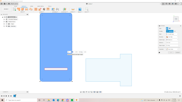
After I had a rough idea of how my handphone stand would look like, i used the fusion 360 software to create a 3d design of my phone stand.

I first created a base sketch of my phone stand. since i planned to use parametric to help in my phone stand, i created a user parameter naming it thickness to account for the various material thickness that might be available for laser cutting.

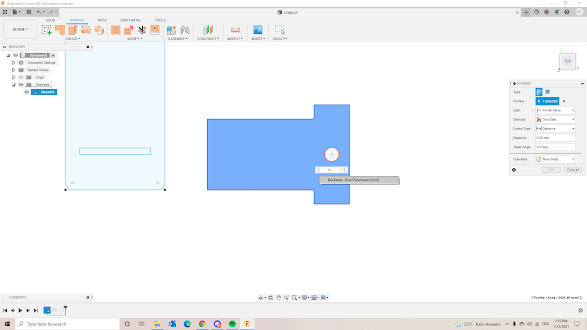
After creating the main shape for the handphone stand, i created a slot in the right shape with dimension similar to the left shape to slide in. The slot dimensions was linked to the thickness of the material.
i then extrude both shapes with the dimensions as 'thickness'. meanwhile i created a hole to allow the phone to be charged while on the stand.


After extruding the shapes, i was basically done. 
here is an image to show how the parametric would work. If the material provided is 10mm thick, i can easily change by going into the change parameter setting and changing the expression.
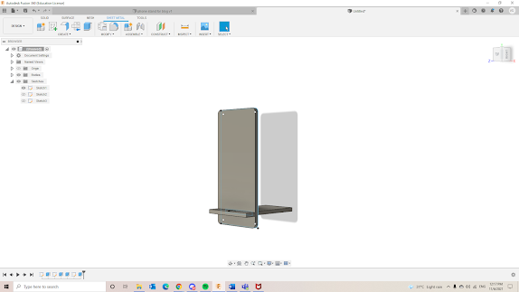
This is how the handphone stand would look like after slotting the two parts together. when placed on a flat surface, the phone stand would be leaning slightly.


And that's it, the completed handphone design.

Have a look at my handphone stand below